Multi-stage pressure reduction in mining applications
In the field of industrial flow handling equipment, pressure reduction often needs to be managed in a controlled and staged manner, a process known as multi-stage pressure reduction. This approach is crucial across various applications, including slurry transport pipelines, hydro dams, power generation, oilsands processing, and other multi-phase flow scenarios. The design goals and guidelines for these pressure-reducing systems can vary widely depending on the specific application.
Each multi-stage pressure reduction system has a unique design objective tailored to its process control requirements. For instance, in slurry transport pipelines within the mining industry, the goal might be to prevent Slack Flow — a condition that can damage equipment and cause instability. Alternatively, for multi-phase slurry fluids, the goal may be to avoid turbulent phenomena like cavitation and sudden pressure drops that could lead to excessive flocculation.
This article explores the diverse applications of multi-stage pressure reduction systems, their design goals, and the flow equipment used in different scenarios.
Applications of multi-stage pressure reduction

To illustrate the wide spectrum of applications requiring multi-stage pressure reduction, we present three distinct cases, each highlighting a specific design approach and flow equipment configuration necessary to meet process flow control objectives.
Application 1: Multi-phase oilsands tailings
In this scenario, a three-phase oilsands tailings fluid must undergo a significant pressure drop. Attempting to achieve this pressure reduction in a single stage could lead to cavitation (bubble formation) and potential erosion damage, as well as undesirable changes in the fluid’s properties. Maintaining the key fluid properties of tailings fluids are crucial for optimizing water and land reclamation efforts.
To prevent damaging impacts of this high-pressure drop application, the system must be carefully analyzed, and equipment and design protocols should be followed. Because of the complexity of these processes, the most effective way to achieve this is customizing the device to achieve the predefined needed conditions. The proven approach employed here for managing this multi-stage pressure reduction was in two stages with following details:
- First stage: This pressure drop stage utilizes a custom trim control valve to handle the initial pressure drop while maintaining minimal fluid shear impact.
- Second stage: In this stage, an orifice plate, with an eccentric orifice hole, positioned downstream of the control valve further reduces pressure to the desired control requirement.
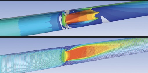
For similar multi-phase applications where dispersed solids are closely monitored, predicting the shear rate of the fluid as it flows through the valve and/or orifice plate is essential. Typically, the non-Newtonian behaviour of these fluids makes their analysis ideal candidates for computational fluid dynamics (CFD) simulations. However, accurate rheology and mathematical models are still required to predict the shear-sensitive flow behavior of these fluids. With the right inputs and simulation techniques, CFD simulations can help optimize valve trim designs, study shear rates, turbulence, and velocity gradients, ultimately enhancing the performance of the flow components.
Application 2: Choke stations for slurry transport pipeline to prevent slack flow
In mining operations, slurry transport pipelines often traverse significant elevations. The resulting changes in pipe velocity and inclination can cause “slack flow,” leading to pipe damage, vibration, and erosion.

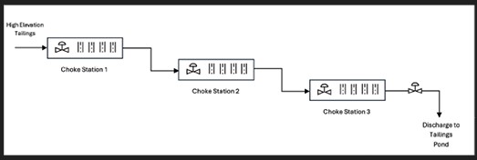
The “slack flow” phenomenon can be prevented by designing the pipe to have discrete and staged pressure reduction areas called “choke stations”. Each choke station would be designed with different flow equipment to reduce a certain amount of head pressure which is typically based on eliminating cavitation.
Depending on the design goals and process conditions, each choke station may require different flow equipment to meet the desired objectives. In a specific application, a system was designed with three choke stations where each station featured one custom control valve and four orifice plates – each with a progressively larger orifice hole diameter. The setup also features a custom control valve downstream of the three choke stations to manage back pressure if needed, thereby achieving the multi-stage pressure reduction.
Overall, there could be multiple choke stations from the highest to the lowest elevation of the pipeline, each contributing to the discrete multi-stage pressure reduction required. In mining applications, where tailings have high solid concentrations and flow at high velocities, the environment can be particularly abrasive for flow equipment such as control valves and orifice plates. Therefore, the equipment must be specifically designed to handle abrasive fluids. Additionally, precise sizing calculations are critical to the ultimate performance of the choke stations.

Application 3: Fixed Orifice multi-stage pressure reduction
In this third application, we examine a hydro power example where only fixed orifice plates were employed for multi-stage pressure reduction.
From a system design perspective, using fixed orifices for pressure reduction offers less flexibility for variations in pressure drop as flow rates change. In contrast, incorporating control valves with orifice plates provides greater flexibility for systems with significant changes in volume flow rates and pressures. However, in certain hydrostatic gravity-fed applications where the flow rate is stable with only minor fluctuations and a fixed pressure head, using multiple fixed orifice plates in series can be an effective solution.

For instance, in one hydro dam application, two fixed ASME 600 pressure class orifice plates were used to reduce the high inlet pressure before reaching a pump station. This setup was designed to protect downstream equipment rated for lower pressures, such as ASME 300 pressure class. Each orifice plate in this application was specifically designed to reduce a prescribed head pressure at a fixed flow rate.
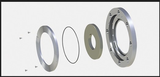
In this and similar applications, it is ideal to design the orifice plates with a field-replaceable insert. This design allows for changing the pressure drop characteristics of each orifice plate by simply replacing the internal insert with a different orifice hole. This approach provides the end user with the flexibility to experiment with various orifice sizes and install the one that delivers the desired performance in the field.

Pressure reduction is a common aspect of any process fluid handling system; however, managing multi-stage pressure reduction in abrasive and multi-phase fluids presents significant and complex challenges. These applications can involve pressure reductions exceeding 6,895 kPag, handling complicated multi-phase slurry mixtures with unique properties, and operating in extremely abrasive environments with a high potential for erosion damage to flow equipment.
Addressing these challenges and designing effective flow equipment requires sound engineering practices and reliable field proven designs. Each multi-stage pressure reduction application may present new challenges and demand unique system design solutions to meet process goals.
Kareem Lemboye, M.Sc., P.Eng., is a design engineer at Special Alloy Fabricators.
Comments