Simplifying drillhole planning

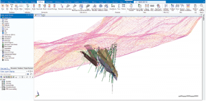
Topographic digital terrain model (DTM) with orebodies and deep drillholes Credit: MicroMine
Planning drillholes for a project was once a tedious process. However, with modern technology, planning drillholes – be it a shallow reconnaissance program or a series of deep drillholes – can be accomplished with ease. Drilling in widely spaced projects that doesn’t require extensive targeting can be planned using an approach appropriate for wide, shallow drillholes in a classic grid pattern (known as a reconnaissance program).
In an advanced project where targeted drilling is required, a deeper drillholes may be more suitable or required. These drillholes are generally closely spaced and cover a smaller area compared to reconnaissance drilling programs. Targeted drilling is generally geared towards targeting a certain structure at some depth and deviation in the drill path with increasing depth must be accounted for. Both targeted and shallow drillhole programs concentrate on different stages of exploration; shallow programs are a good first pass, giving an overall picture of the property (for example, grade trends and general orientations) with little detail, while deep programs allow the exploration team to collect detailed information that is depth and orientation specific.
Using an exploration modelling software such as Micromine, shallow reconnaissance programs can be planned with ease. A pattern of regularly spaced holes is defined and can be automatically generated in a modelling product, with control over their orientation and spacing. Input data is as simple as deciding on your hole and line spacing (considering budgetary constraints and size of the area of interest), extents of the project boundary and hole depths.
The last thing to consider is where the collar of each hole is located. If your topography is known, Micromine can simply assign a Z value to each collar based on where it would intersect with the topography. Otherwise, you can set a constant value for elevation. Using a 3-D product allows you to adjust the pattern using visual cues, such as interactively shifting the origin and adding or subtracting holes as needed. With the right parameters ready to go, this process only takes a matter of minutes!
Planning deep hole campaigns
While planning deep hole programs is more intensive than shallow programs, the process is still straightforward. There are two main types of prospective holes to plan – holes that originate at the collar and extend at some orientation (from collar) and holes that start at a target and project to the collar (from target). Both types can be planned with a few simple steps in Micromine, using digital strings to represent the hole trajectory. Defining these strings to intersect orebodies or relevant features is as easy as a point-and-click action by working through easily defined cross sections in your project. It is common to start at one end of the project and move through the deposit in predefined section increments.
The natural way to plan a hole when the collar location is fixed, is to start the hole at the collar and extend the string for the defined length, initial orientation and optionally, deviation. Alternatively, if the target location is fixed and the collar is variable, the hole is effectively planned in reverse. The trick to keep in mind while planning from the target holes is to flip the string direction once it has been planned, as you won’t actually be drilling from the target, but from the collar location you defined via the string. Micromine also provides the option to extend the string beyond the target to appropriately define the waste boundary.
After you have stepped through your sections, defined your representative strings, and are satisfied with the locations and orientations of your proposed drillholes, the next step is to annotate the strings with relevant drillhole data. Such data can include labels for collar name, length of hole, azimuth, and inclination. These annotations give a concise snapshot of the area that any user can quickly get information from.
The final step after annotating the string layer is to convert the representative strings into collar and survey drillhole files. This may seem daunting, but is quite straightforward. Simply input the string file you just created while planning your drillholes and define the names of your output collar and survey files. Micromine internally defines each hole by linking successive downhole surveys with a series of 3-D spherical arcs (also known as the minimum curvature method). These arcs are then approximated to produce straight-line segments. All planned holes will then appear as regular drillholes in your project, including collar names, azimuth and inclination data and can be separated into its own “planned” drillhole database. This data can be easily packaged for delivery to drilling contractors ensuring a seamless and successful drilling program. Any project can also easily be shared with colleagues or relevant parties and viewed using Micromine MFX.
Holly McKague is a technical consultant and product specialist with Micromine.
Comments